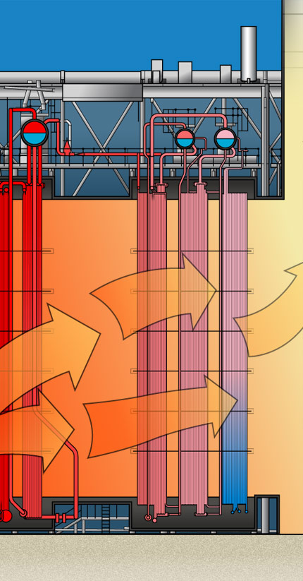
ESB Logo

To view this presentation, you will need to upgrade your browser to a modern version for security and performance improvements. Visit Browse Happy to find out more.

If you are using a legacy version of Internet Explorer, please also ensure that 'Compatibility Mode' is turned off.


To view this website, please turn your device around into 'landscape' mode.

ESB Logo

Unfortunately you cannot view the presentation unless your browser window is 1024 x 700 pixels or bigger in size. Please try resizing your browser or using a bigger screen.

You may also try adjusting the 'zoom' value to 90% or less if your browser supports this feature, but please be aware that this will reduce the visual clarity of the presentation.

Heat Recovery

As the hot exhaust gasses pass through the HRSG, the water contained in various tube bundles is heated. This turns to steam, and is sent to and from the Steam Turbine.

  • The HRSG: A System Of Three Circuits

    The HRSG houses an elaborate interconnecting system of pipes. Within the system there are three independent circuits, and each one is actually a water boiler. The combined effort of the three circuits supplies superheated vapour to the Steam Turbine, where the heat is converted into mechanical energy and then it is sent via a shaft to the Electrical Generator.

    A graphic showing how Work Done = Force x Distance

    One boiler is driven by high pressure, another loop operates off intermediate (middle) pressure while the third boiler works under low pressure. The conversion of liquid water into superheated vapour is a four step process with each of the three circuits supplying a stream of vapour that carries within it high grade heat (dense thermal energy) which is put to work driving the Steam Turbine. The vapour displaces the turbine, and thus work is done.

  • The HRSG: Liquid Water to "Superheated Steam" in Four Steps
    A graphic showing how Work Done = Force x Distance

    Step 1: Economiser / Preheater

    Feedwater hits the Econmiser and it is heated up until its temperature is close to boiling point. In the case of the Low Pressure (LP) circuit we use the Preheater. This water then travels to the relevant Evaporator depending on whether it is on the HP, IP or the LP circuit.

    Step 2: Evaporator

    This converts the hot liquid water into steam (which is a mixture of vapour and water droplets). The steam then travels to the relevant drum in order to detach the vapour fully.

    Step 3: Steam Drum

    Within the drum saturated steam is detached fully from the liquid droplets using centrifugal forces and gravity (See 3.6). Each water circuit has its own drum as indicated on the animation.

    Step 4: Superheater

    The detached saturated vapour leaves the drum and is then superheated up to temperatures of 330°C. It is this superheated vapour that carries the high grade heat / dense thermal energy to the Steam Turbine. After passing through the turbine the H20 is returned to the HRSG as water condensate and cycle starts again. The vapour passes through a scrubber (filter) and this removes any solid particles present. The vapour from each drum then enters the pipeline and it then runs across to the Steam Turbine.

  • The HRSG: Why is water used?

    The Specific Heat Capacity (SHC) of water is 4200 J/kgK which is very high. This allows the material to carry a large volume of thermal energy within a small mass quantity. The SHC of H2O per degree increases exponentially when it is superheated, thus allowing H20 to carry even more energy per unit mass. There is also latent heat to consider during this change of state, which in this case is the latent heat of vaporisation.

    A formula: E = m.c.θ