ESB Logo

To view this presentation, you will need to upgrade your browser to a modern version for security and performance improvements. Visit Browse Happy to find out more.

If you are using a legacy version of Internet Explorer, please also ensure that 'Compatibility Mode' is turned off.


To view this website, please turn your device around into 'landscape' mode.

ESB Logo

Unfortunately you cannot view the presentation unless your browser window is 1024 x 700 pixels or bigger in size. Please try resizing your browser or using a bigger screen.

You may also try adjusting the 'zoom' value to 90% or less if your browser supports this feature, but please be aware that this will reduce the visual clarity of the presentation.

 
  • The Water-Steam Cycle

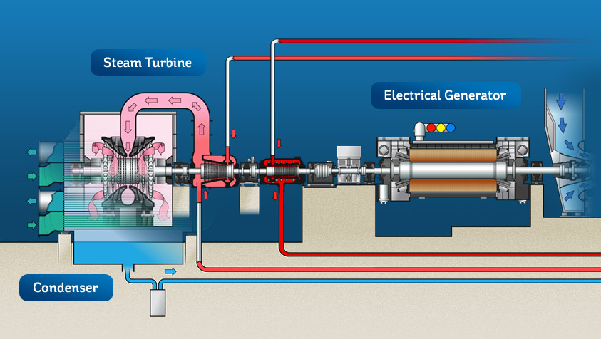
    The gas exhaust flue supplies heat to the HRSG, where it is used to generate steam. The vapour travels from the HRSG via pressurised pipelines where it is used to drive three sections of the Steam Turbine. This process converts the thermal energy of the steam into kinetic (rotational) energy which is sent by a fixed shaft to the Electrical Generator to be then converted into electrical energy. The fixed shaft arrangement is illustrated opposite.

    Once the vapour has fully passed through the blades of the turbine it enters the Condenser section where it undergoes a change of state back into water. This liquid form can then be efficiently re-sent to the HRSG so as to continue the Water-Steam Cycle.